Products
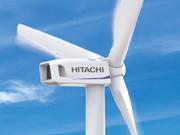
HITACHI 5,200kW Wind Turbines bring out more power from vast windy oceans.
Ocean winds are stronger yet more unpredictable.
The technology of Hitachi 5,200kW Downwind Turbine allows to efficiently harvest the power of the offshore wind.
Features
Reliable Technologies of Downwind Rotor

As is an inherent in the physics of a downwind configuration, the stronger the wind, the larger the clearance between the blades and the tower by blade flexion. This results in a lower probability of a tower hit. In case of stand still mode, downwind turbine switches to a free yaw operation mode and wards off the cross wind by the weather vane principle without yaw control even in case of black out conditions. This, in principle, reduces overturning moment to the foundation or floaters and maintains high degree of safety. That is important especially for offshore projects. Also, the wind sensors installed at the front of the blades give a more precise wind direction and speed in the upper stream. Yaw and blade pitch shall also be modulated to the right angle for more production.
Lightning Protection System

HTW5.2-127 and 136 secure lightning protection for electric charge of 600C,which is above IEC standard. The major components withstand 95 percent of lightning strikes. The protection level exceeds the IEC Class I standards. For protection against induced lightning,electrical and control panels are equipped with Surge Protection Device in each Lightning Protection Zone.
| Protection level | Peak current [kA] |
Particular energy [kJ/Ω] |
Total electrical charge transfer [C] |
|---|---|---|---|
| IEC I | 200 | 10,000 | 300 |
| HTW5.2-127 HTW5.2-136 |
250 | 40,000 | 600 |
To ensure power train reliability accelerated life tests on mechanical and electrical nacelle components are performed by adding complexed load.
*
The severity and frequency of a lightning strike cannot be forecasted as it is a natural phenomenon. The above description shall not apply to all cases.
Fault Ride Through Verification

Hitachi wind turbines comply with FRT requirement regulated by Japanese Grid-interconnection Code(JEAC9701-2012). Turbines stay connected in short periods of voltage dip. Hitachi performed verification tests of the FRT function with the active power grid. The verifications for the other regions are in progress.
* FRT:Fault Ride Through
Reliable Protection System and Structure

The steel monopole tower structure was designed with partitions to preserve the closed environment inside the electric module from humidity and airborne salt for installations in both offshore and onshore by the sea.
Advanced System Configuration

A forte of 5,200kW Wind Turbine is the passive cooling systems. The radiator located at the front of nacelle increases the effectiveness of the cooling. The radiator exchanges the heat of the cooling water from the generator and gearbox efficiently with fresh air caught in the upper stream at the front of nacelle. The outside cooling air is exhausted to Left-, right and lower sides of the nacelle, never entering the nacelle. A pressurization device is provided as an option for the extra prevention of outside air entering into the turbine.
*
The pressurizing device is optional.
Power Curve

Specification
| HTW5.2-127 | HTW5.2-136 | ||
|---|---|---|---|
| Rotor | Rotor Diameter | 127m | 136m |
| Swept Area | 12,644m² | 14,540m² | |
| Rotor Position | Downwind | ||
| Rotating Speed | 6.4~12.7m-1 | ||
| Rated Rotating Speed | 11.7min-1 | ||
| Rotating Direction | Clock-wise (from wind direction) | ||
| Blades | No. of Blades | 3 | |
| Length | 62m | 66.5m | |
| Material | GFRP | ||
| Transmission | Gear Ratio | 1: 40 (approximately) | |
| Generator | Rated Power | 5,200kW | |
| Type | PGM | ||
| Power Conditioning System | Full Converter | ||
| Fault Ride Through | Standard | ||
| Set-up Transformer | Output Voltage | 33,000V / 1,800V | |
| Nacelle | Material | GFRP | |
| Tower | Type | Steel Monopole Tubular Tower | |
| Hub Height | 90m(minimum) | ||
| No. of Segments | 3 | ||
| Brake System | Power Control | Pitch Control, Variable Speed | |
| Cut-in wind speed | 4m/s | 3.5m/s | |
| Cut-out wind speed | 25m/s | ||
| Emergency Brake | Blade Feather (independently controlled) Disc Brakes |
||
| Yaw control | Active Yaw(normal operation) Free Yaw(storm condition) |
||
| Environmental Condition | Annual Average Wind Speed | 10m/s | 7.5m/s |
| Wind Class (fatigue) |
Ⅰ | Ⅲ | |
| Wind Class (extreme) |
T | S | |
| Extreme Wind Speed(Vref,T) | 57m/s | 55m/s | |
| Turbulence Category | A | ||
| Operating Temperature | -20~40℃ | ||
| Altitude | lower than 1,000m | ||
*
The above information is therefore subject to change without prior notice.
Schematic drawing

*
The above information is therefore subject to change without prior notice.

